This model is especially pertinent to connectors, where a few millimeters of PM fiber are cemented into a ferrule and end polished. Shrinking of the cement and the different expansion coefficients of the materials contribute to external stress induced changes in the rotational orientation of the axes. The angle tolerance on the input orientation of the plane polarized input further contributes to cross coupling as does the tolerance on connector to connector axis alignment within an adapter, or a fusion splice.
Polarization Modes
There are many texts and references that describe the orthogonal polarized modes (the eigenmodes) that propagate in a singlemode fiber. This section reviews some definitions and compares singlemode and PM fiber.
Polarization dependant insertion loss
This is due to the difference in coupling or loss between polarization modes as they propagate through a component such as a singlemode coupler. The difference may be dependent on the orientation of the component.
Polarization mode dispersion
In a perfect fiber the polarization modes have the same propagation constant and will travel equal distances and have identical phase. If plane polarized light is launched it will split into two identical orthogonal modes that subsequently recombine to give the same plane polarization. In the real world there are small manufacturing variations in the fiber, as well as bend induced stress, that cause minor areas of birefringence. This in turn creates optical axes with differing orientation and propagation constants which change the plane polarization to elliptical polarization.
A pulse traveling along a fiber is subject to splitting, accumulating components of different phases and recombining to give elliptically polarized light developing a pulse spread due to the accumulated phase changes and axis rotations.
The simulation program PMdisp V 1.0 models the spread of a pulse as it travels down a singlemode fiber.
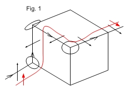
Polarization rotation
The plane of polarization is rotated in a singlemode fiber dependent on the path layout. Figure 1 shows a 90 deg. rotation. As orthogonal polarization modes will not interfere there is signal fading in interferometers made from singlemode fiber. Polarization controllers are made from fiber loops that induce a controlled amount of birefringence as well as polarization field rotation to compensate.