
Product Data 905(P)/905(P)-MPolarization Maintaining
|
 |
Model 905(p) variable ratio couplers are made with optically contacted polished fibers mounted in substrate blocks that have transverse motion in the contact plane to adjust core-to-core separation distance. In the case of PM fiber, the orientation of the fast and slow axes is preserved during the motion. A negligibly thick oil layer is used to lubricate the substrate blocks and ensure smooth motion. Long term ratio stability is better than 1% under laboratory conditions.
Fine transverse motion is accomplished by means of a micrometer and lever system. The 25:1 lever ratio gives approximately one micron of motion at the coupler center per 0.001 inch division on the micrometer.
This motion however, is not free of hysteresis or backlash and a particular micrometer reading or selected position for the remote 905-M driver will not correspond to a particular fixed ratio, only to a nominal ratio. Accurate ratio settings can only be made by observation of the outputs. (X and Y if input A or B). Hysteresis and backlash tend to be reduced if the device is used repeatedly.
Available fibers have cutoff wavelengths ranging from 710 nm to 1550 nm. For a particular fiber used in a variable coupler the useful bandwidth extends from the single mode cutoff wavelength to approximately 1.3 times the cutoff wavelength, where losses begin to occur.
|
The Model 905(P)-M is the Model 905 variable ratio coupler, the ratio can be remotely controlled with a PC (through a USB port) using a New Focus Picomotor™ and Controller/Driver. The Picomotor can also be adjusted using the manual hand knob adjustment. The knob can be rotated while the motor is plugged into the driver and the driver is on but not driving the motor. The drive pulses are only sent to the Picomotor when commanded to by the controller. Picomotor drivers (8742-4-KIT) which provide computer control via USB and Ethernet communication interface are supplied or can be purchased directly from Newport. Both interfaces are well supported via Windows DLL, sample LabVIEW™ VIs, and intuitive graphical user interface (GUI) Windows application with device auto-discovery feature. The 905(P)-M is not calibrated for motor position vs. coupling ratio. The Picomotor is simply a method of remote adjustment. Units are shipped in a nominal 50/50 ratio position at the stated wavelength of operation. Ratio settings are made by observation of the output powers (X and Y if input A or B). |
.jpg) |
(room temperature,measured after connectorization):
-24 dB typical
-22 dB guaranteed
0-99% (other ranges upon request)
<0.15dB
1m standard length (longer available)
sleeved in 900 micron HYTREL or 3mm sleeving
0.750 to 2.04um
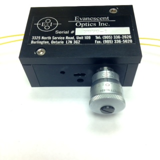
905(P): 31 mm x 46 mm x 69 mm aluminum case, with micrometer projecting 30 mm; 905(P)-M has Newfocus Motor projecting 42 mm, dimension can be found here.
FC/SPC, FC/APC, LC/APC, SC/APC, SC/PC Standard is keyed to slow axis, keyed to fast axis on request